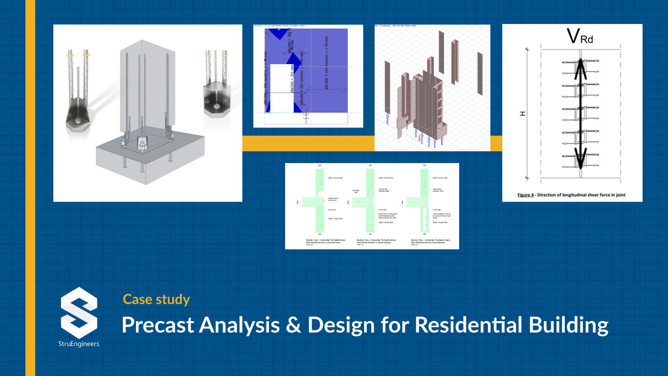
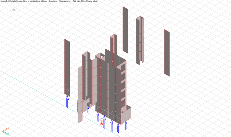
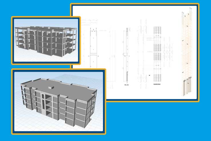
This case study aims to present an overview of the structural design for a Residential building with a focus on the inclusion of precast wall elements in the structure, which as per the original design were proposed to be cast-in-place.
The building comprises three wings, each between 5 and 7 stories high. This study specifically addresses Building 5 and wing 2.
The Precast Design Proposal
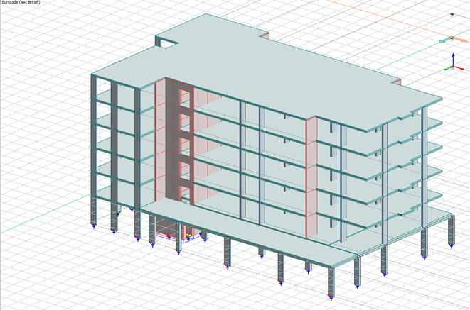
The design envisions a strategic shift to precast elements while preserving the structural integrity of the original proposal. Precast wall elements, 200 mm thick reinforced concrete panels, will replace certain components from the original design. The structural framework features robust reinforced concrete flat slabs that rest upon a strategic combination of blade columns, shear walls, and cores. Notably, the structural integrity of the building is enhanced by the presence of shear walls and core walls, strategically positioned around the stairs and lift area.
Precast Wall Specifications
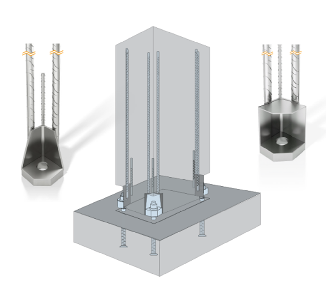
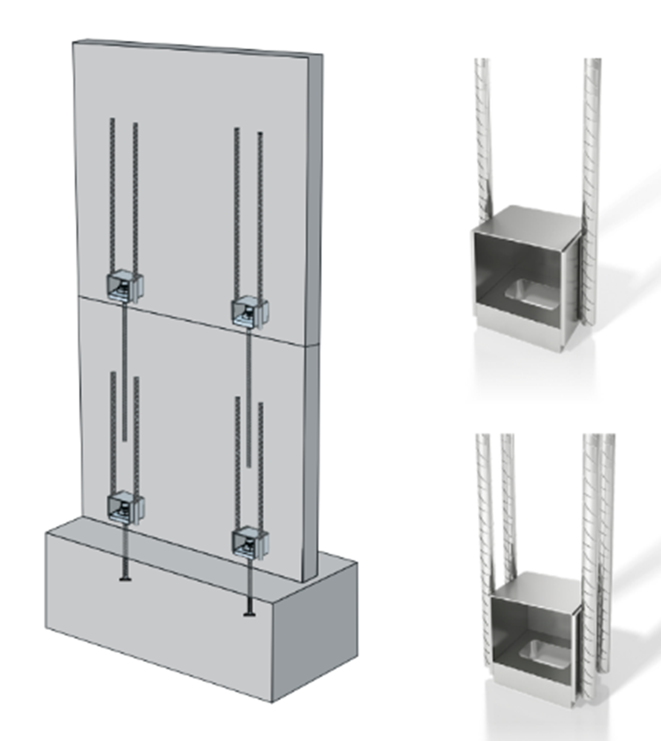
- Construction: Modularized precast panels with horizontal joints utilizing proprietary anchors and vertical ties.
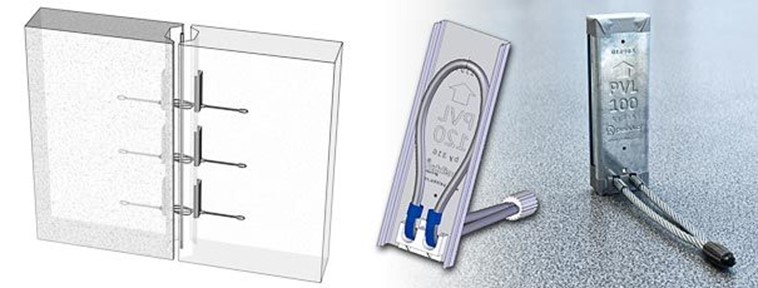
- Joining Mechanism: Threaded bars, shoe units, and wire rope loops, enhancing both vertical and horizontal load distribution.
- Safety Measures: Supplementary reinforcement at slab level above vertical wall joints to resist shear forces.
Loading/Design Codes
The structural design adheres to established codes and loading considerations:
Design Codes: Utilization of Eurocodes (EC1 & EC2) for structural design.
Load Combinations: Design for both, the ultimate and the serviceability limit states as per EC1 & EC2.
Material Specification
- Concrete Grade: C30/37
- Cover: 30 mm
- Reinforcement Grade: 500 MPa
- Fire Resistance: 60 minutes (meeting BS EN 1992-12 requirements)
FEM Analysis
Model Description
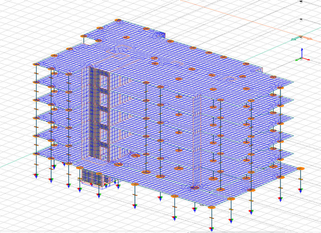
The complete building has been meticulously modeled using FEM-Design Software, with a special emphasis on design skills rather than the software features. The lateral stability model assumes all columns as pinned connections with adjusted meshing properties for vertical joints between precast walls.
Results
- Lateral Displacement
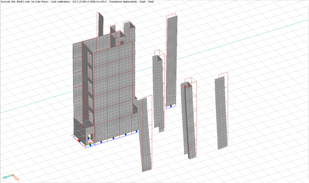
Analysis results from the FEM model are utilized to determine the maximum lateral displacement on the shear stability elements based on the Serviceability Limit State (SLS) maximum load combination envelope (a range or set of forces or loads that the structure night experience during its service life) and checked for allowable deflection, a figure which should not exceed the value of the maximum of height of structure divided by 500.
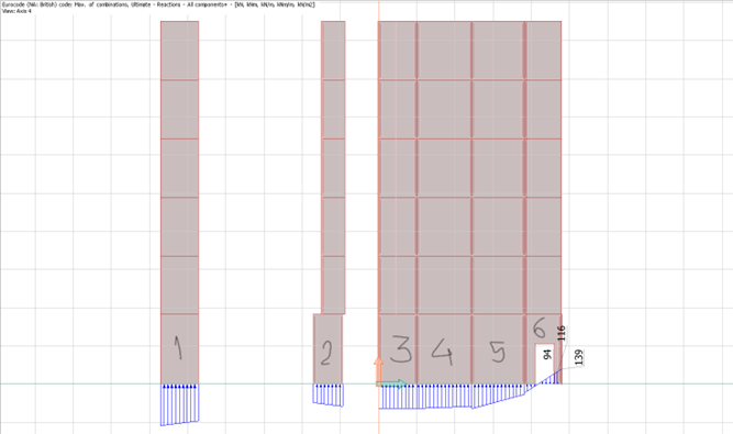
- Vertical Reactions/Compression/Uplift
Analysis results from the FEM model are utilized to determine the maximum lateral displacement on the shear stability elements based on the Serviceability Limit State (SLS) maximum load combination envelope (a range or set of forces or loads that the structure night experience during its service life) and checked for allowable deflection, a figure which should not exceed the value of the maximum of height of structure divided by 500.
Determining Dowels/Starter/Boxes
Uplift force results from FEM analysis help in determining the number and type of dowels / starter boxes required. The number & type will depend upon the precast vendor’s specifications.
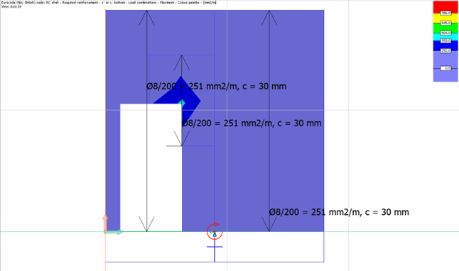
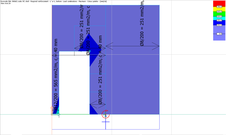
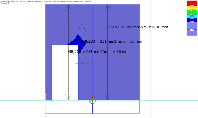
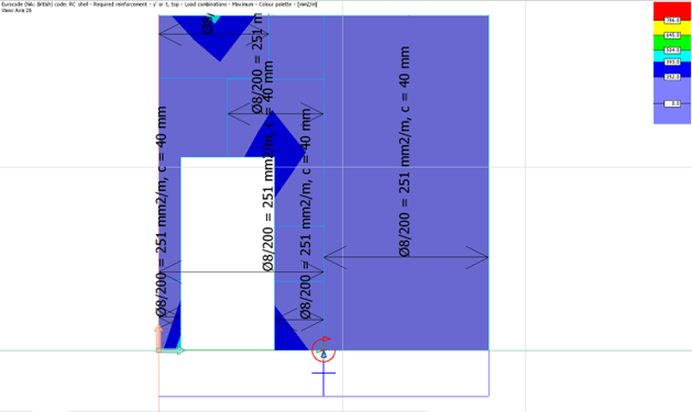
Reinforcement maps
We have the option to utilize the rebars generated by the software or manually determine our own reinforcement layout using the reinforcement maps displayed in the image above.
– Horizontal and Vertical Ties
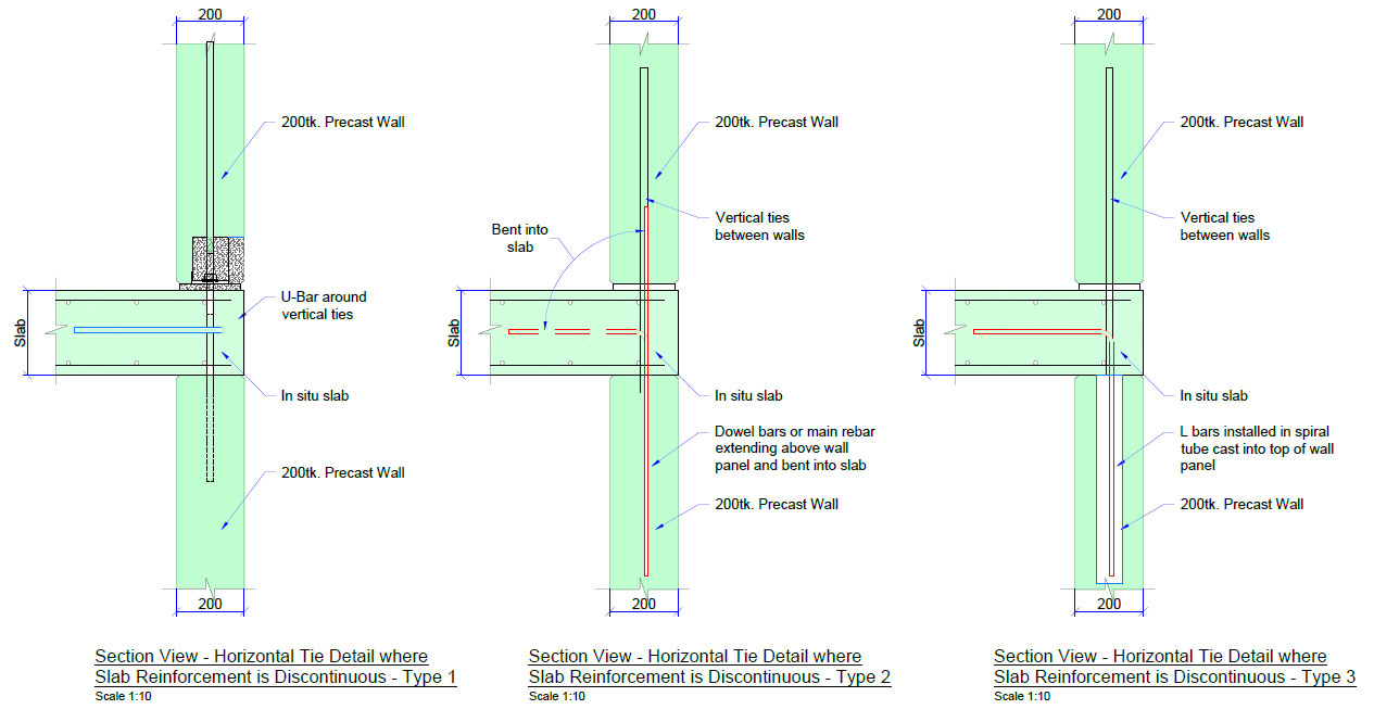
To ensure structural robustness against local failure (element-specific failure in the structure), both horizontal and vertical ties have been meticulously provided, in alignment with the relevant design standards or clauses.
– Shear Across Vertical Joints/Loop Bars
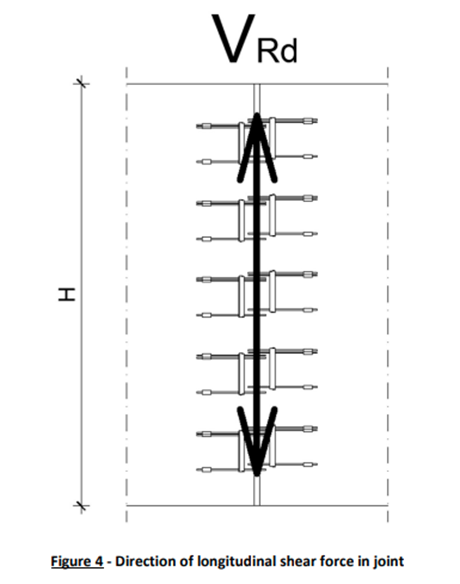
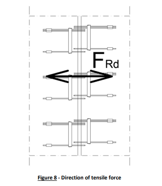
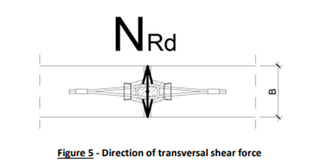
To address localized shear forces on vertical panel joints, a dual mechanism involving specialized wire loop boxes is employed. This includes conservative design considerations and calculations based on the precast vendor’s Technical Manual.
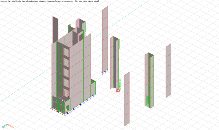
These forces are determined from FEM Design and Wire loop types are assigned using technical manual.
Conclusion
This case study underscores our capability in innovative structural design (precast design), leveraging precast elements and Finite Element Analysis for optimal performance. The emphasis on safety, compliance with design codes, and a meticulous approach to FEM analysis showcases our commitment to excellence in the realm of residential building design.
